 |
| March 23, 2021 | Volume 17 Issue 12 |
Designfax weekly eMagazine

Archives
Partners
Manufacturing Center
Product Spotlight
Modern Applications News
Metalworking Ideas For
Today's Job Shops
Tooling and Production
Strategies for large
metalworking plants
Tiny accelerometer uses laser light instead of mechanical strain to produce a signal
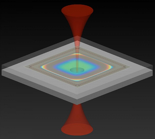
Illustration of an optomechanical accelerometer that uses light to measure acceleration. The NIST device consists of two silicon chips, with infrared laser light entering at the bottom chip and exiting at the top. [Credit: F. Zhou/NIST]
You're going at the speed limit down a two-lane road when a car barrels out of a driveway on your right. You slam on the brakes, and within a fraction of a second of the impact an airbag inflates, saving you from serious injury or even death.
The airbag deploys thanks to an accelerometer -- a sensor that detects sudden changes in velocity. Accelerometers keep rockets and airplanes on the correct flight path, provide navigation for self-driving cars, and rotate images so that they stay right-side up on cellphones and tablets, among other essential tasks.
Addressing the increasing demand to accurately measure acceleration in smaller navigation systems and other devices, researchers at the National Institute of Standards and Technology (NIST) have developed an accelerometer a mere millimeter thick that uses laser light instead of mechanical strain to produce a signal.
Although a few other accelerometers also rely on light, the design of the NIST instrument makes the measuring process more straightforward, providing higher accuracy. It also operates over a greater range of frequencies and has been more rigorously tested than similar devices.
Not only is the NIST device, known as an optomechanical accelerometer, much more precise than the best commercial accelerometers, it does not need to undergo the time-consuming process of periodic calibrations. In fact, because the instrument uses laser light of a known frequency to measure acceleration, it may ultimately serve as a portable reference standard to calibrate other accelerometers now on the market, making them more accurate.
The accelerometer also has the potential to improve inertial navigation in such critical systems as military aircraft, satellites, and submarines, especially when a GPS signal is not available. NIST researchers Jason Gorman, Thomas LeBrun, David Long, and their colleagues describe their work in the journal Optica.
VIDEO: This animation demonstrates the operating principles of the new accelerometer. This optomechanical accelerometer consists of two silicon chips. The first chip has a proof mass suspended by a set of silicon beams, which allows the proof mass to move vertically. The top of the mass has a mirrored coating. The second chip has an inset hemispherical mirror. Together, the mass and hemisphere mirrors form an optical cavity. Infrared laser light is directed into the device. Most frequencies are reflected entirely. However, light matching the resonant frequency builds up inside the cavity, increasing in intensity, until the intensity of the light transmitted by the cavity matches the input. Light transmitted by the cavity can be detected on the other side. When the device accelerates, the length of the cavity changes, shifting the resonant frequency. By continuously matching the laser to the resonant frequency of the cavity, researchers can determine the acceleration of the device. [Animation: Sean Kelley/NIST]
The study is part of NIST on a Chip, a program that brings the institute's cutting-edge measurement-science technology and expertise directly to users in commerce, medicine, defense, and academia.
Accelerometers, including the new NIST device, record changes in velocity by tracking the position of a freely moving mass, dubbed the "proof mass," relative to a fixed reference point inside the device. The distance between the proof mass and the reference point only changes if the accelerometer slows down, speeds up, or switches direction. The same is true if you're a passenger in a car. If the car is either at rest or moving at constant velocity, the distance between you and the dashboard stays the same. But if the car suddenly brakes, you're thrown forward and the distance between you and the dashboard decreases.
The motion of the proof mass creates a detectable signal. The accelerometer developed by NIST researchers relies on infrared light to measure the change in distance between two highly reflective surfaces that bookend a small region of empty space. The proof mass, which is suspended by flexible beams one-fifth the width of a human hair so that it can move freely, supports one of the mirrored surfaces. The other reflecting surface, which serves as the accelerometer's fixed reference point, consists of an immovable microfabricated concave mirror.
Together, the two reflecting surfaces and the empty space between them form a cavity in which infrared light of just the right wavelength can resonate, or bounce back and forth, between the mirrors, building in intensity. That wavelength is determined by the distance between the two mirrors, much as the pitch of a plucked guitar depends on the distance between the instrument's fret and bridge. If the proof mass moves in response to acceleration, changing the separation between the mirrors, the resonant wavelength also changes.
To track the changes in the cavity's resonant wavelength with high sensitivity, a stable single-frequency laser is locked to the cavity. As described in a recent publication in Optics Letters, the researchers have also employed an optical frequency comb -- a device that can be used as a ruler to measure the wavelength of light -- to measure the cavity length with high accuracy. The markings of the ruler (the teeth of the comb) can be thought of as a series of lasers with equally spaced wavelengths. When the proof mass moves during a period of acceleration, either shortening or lengthening the cavity, the intensity of the reflected light changes as the wavelengths associated with the comb's teeth move in and out of resonance with the cavity.
Accurately converting the displacement of the proof mass into an acceleration is a critical step that has been problematic in most existing optomechanical accelerometers. However, the team's new design ensures that the dynamic relationship between the displacement of the proof mass and the acceleration is simple and easy to model through first principles of physics. In short, the proof mass and supporting beams are designed so that they behave like a simple spring, or harmonic oscillator, that vibrates at a single frequency in the operating range of the accelerometer.
This simple dynamic response enabled the scientists to achieve low measurement uncertainty over a wide range of acceleration frequencies -- 1 to 20 kHz -- without ever having to calibrate the device. This feature is unique because all commercial accelerometers have to be calibrated, which is time consuming and expensive. Since the publication of their study in Optica, the researchers have made several improvements that should decrease their device's uncertainty to nearly 1%.
Capable of sensing displacements of the proof mass that are less than one hundred-thousandth the diameter of a hydrogen atom, the optomechanical accelerometer detects accelerations as tiny as 32 billionths of a g, where g is the acceleration due to Earth's gravity. That's a higher sensitivity than all accelerometers now on the market with similar size and bandwidth.
With further improvements, the NIST optomechanical accelerometer could be used as a portable, high-accuracy reference device to calibrate other accelerometers without having to bring them into a laboratory.
Learn more:
Paper 1: F. Zhou, Y. Bao, R. Madugani, D.A. Long, J.J. Gorman, and Thomas W. LeBrun. Broadband thermomechanically limited sensing with an optomechanical accelerometer. Optica. Published March 8, 2021.
Paper 2: D.A. Long, B.J. Reschovsky, F. Zhou, Y. Bao, T.W. LeBrun, and J.J. Gorman. Electro-optic frequency combs for rapid interrogation in cavity optomechanics. Optics Letters. Published Jan. 29, 2021.
Source: NIST
Published March 2021
*NOTE: Our feedback form isn't working right now. Please send article feedback to mfoley@nelsonpub.com. Thanks!
Rate this article
View our terms of use and privacy policy